

A voltage regulator is built into the vehicle to supply the right amount of energy of DC voltage from the battery to the engine.
In a situation where the voltage regulator fails to control your vehicle’s voltage or there are other voltage issues, what do you do?
Can you bypass the voltage regulator? Yes! you can bypass the voltage regulator on an alternator.
We will go ahead and let you know how to bypass the voltage regulator and what you should look out for in a bad voltage regulator.
Not only will you know how to troubleshoot, but you will also be able to know what to do to fix the issue.
How to Bypass the Voltage Regulator of a PCM
PCM means Powertrain Control Module and bypassing it can resolve the voltage issues as regards the supply problem.
We step-by-step guide you through making an alternator that will do the work of an external voltage regulator.
The process of newly creating an alternator is in two phases – setting up the alternator voltage regulator and connecting the regulator.
To begin the process, you will need to get an aftermarket voltage regulator, regulator plug harness, and wires for connection purposes.
Phase 1: Setting up the Alternator Voltage Regulator
The steps to follow for setting up the alternator Voltage Regulator are:
Step 1 – Wiring Harness with the Alternator
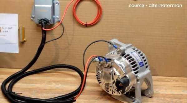
The harness plug comes with two wires. A blue wire and a green wire. The blue wire will be connected to the alternator while the green wire will be connected to the other side of the alternator plug. The red wire is connected to the positive side of the battery.
Your harness can sometimes be two, all you need to do in this case is connect and bring out another wire from the blue wire.
Here is a pro tip for you – the red wire connected to the side of the battery should be connected to a fuse box. This is done to prevent any possible drainage when the engine is turned off.
Step 2 – Taping the wires
Using any good tape, tape up the wires at the connection point for safety purposes. Taping the wires is to protect the wires from any leakage or fuse.
Phase 2: Connecting the External Regulator
Check out the steps to follow in connecting the external regulator to the battery and the ECM panel.
Step 1 – Opening the FrontEngine Hood
The voltage regulator can only be found in the front engine hood. Open the engine hood. Do not open the engine hood when it is hot!
Allow the engine hood to get cold because you will be working with wires. For better precaution, use hand gloves before commencing the wirework.
Step 2 – Blocking all Power Sources
To block all power sources from the battery to the voltage regulator, the terminals of the battery should be disconnected.
The battery is disconnected by detaching both the positive and negative terminals of the battery.
Step 3 – Locate the Voltage Regulator
Locating the voltage regulator is the next step to take after disconnecting the battery terminals. It will be found near the voltage regulator attached to the vehicle computer panel.
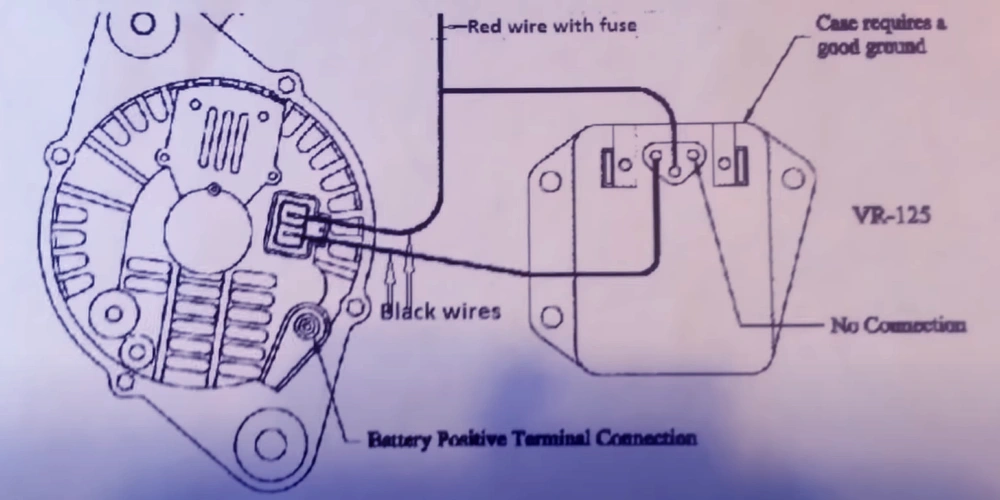
Once you can locate the vehicle computer panel, check for a rectangular-shaped socket. Inside the socket, there will be four visible connected wires. The alternator is to be connected to the voltage regulator wire coming out of the socket.
Step 4 – Mounting the External Alternator
Using bolt screws, mount the alternator voltage regulator on the inner fender or on the firewall. Make sure to use one sheet metal screw for grounding.
Step 5 – Connection of the Wires to the Alternator Voltage Regulator
The green wire coming out of the alternator should now be connected to the bottom post of the voltage regulator.
The green wire should then pass on to the top post of the voltage regulator. The green wire is an output voltage of 12V from a key switch of 12 volts.
Cut off the bad wires that were connected before and isolate them with taping. They are no longer needed.
Step 6 – Connecting a Fuse Box to the Voltage Regulator Switch
Using a voltmeter, find out the 12V key switch from the switchboard panel’s back. The fuse box connection cannot be done unless the 12V key switch is found.
Put a fuse and hook it up into the bottom slot of the switch box.
Step 7 – Connect the Wire to the Battery
The red wire should now be connected to the battery’s positive terminal. The grounding wire coming out of the alternator regulator should go to any ports on the voltage regulator.
At this point, you have completed the bypassing of the PCM voltage regulator.
We promised to let you know how to check for a bad voltage, read on. Here are some of the signs you should check out for in a bad voltage:
- Clusters may stop running properly
- Check for flashing battery lights or check engine light dimming
- Gauge showing an inaccurate reading
- Check the volt gauge for the voltage readings. Check for sudden low or high voltage
- There might be a complete no-voltage reading sometimes
Upon noticing any of the above-listed symptoms of a bad regulator, check your voltage regulator immediately. The fault could be traced to the gauge system.
How to Test Voltage Regulator
A multimeter is used for testing the Voltage Regulator. Follow the steps highlighted below to test for the voltage regulator
Step 1 – Connect the Multimeter
The multimeter comes with two wires. A red and a black wire. To connect your multimeter to the engine battery, connect the red wire to the positive terminal of the battery.
And connect the black wire of the multimeter to the negative terminal of the battery.
When you are done connecting the multimeter to the battery, switch on the power of the multimeter. The power is switched on by turning the knob towards the voltage (V) DC.
Step 2 – Start the Engine
Start the engine to get the voltage reading on the multimeter screen. The multimeter should read around 12.6 volt
Step 3 – Increase the Engine Power
To check if the voltage is increasing with an increase in rpm, the fuel power should be increased and set to idle from 1500 – 2000 rpm.
If it increases with an increased rpm, it only means one thing. The voltage regulator needs replacement or repair.
If the voltage is found to not exceed 12 volts but instead is noticed to be decreasing. It means that the battery is unable to provide a proper power supplement or maybe the alternator is not getting an adequate charge.
In this case, it could only mean that any of the connections are rusty or loosened and have failed to supply the proper voltage. Troubleshoot by checking all the terminals connecting the battery to the voltage regulator.
If the voltage reading remains at or around 12.6 volts. It indicates that the voltage regulator is in perfect working condition and so the problem should be the battery or the gauge.
If the voltage regulator issue isn’t resolved by any of the above methods. Then you should go for the installation of an external voltage regulator bypass. This should resolve all the voltage issues.
“How to Bypass the Voltage Regulator of a GM PCM?”, is one most frequently asked questions. We will answer it for the sake of this article.
How to Bypass the Voltage Regulator of a GM PCM
In the case of a voltage regulator failure in a GM, it is not practical to only consider replacing the failed regulator with a new one.
In a typical GM voltage regulator, when the ignition switch is turned on, current flows through the fuses of the gauges through the battery light and also through the brown wire to the plug on the side or back of the engine.
Once the engine is perfectly running and developing output, the regulator looks internally to check for system voltage.
When it is working well, it puts the complete system voltage back out on the brown wire. With the same voltage on both sides, it turns off.
A failed diode is also a common fault of a GM voltage regulator. Once one fails, you will be able to get only about one-third of the unit’s rated current, i.e. the ripple voltage will be very high.
Zener diodes are usually used to counter the effect of a high ripple voltage when it happens.
Related thought: engine power reduced
Final word
This article is written in so many details that it could easily pass for a complete manual guiding you through the bypassing process of a PCM voltage regulator. All you need to do is consciously follow the steps highlighted above.
We would like to know if this article gave answers to your questions on how to bypass the PCM voltage regulator. Did you try using the steps in this article? Did they help resolve the issues you had with your voltage regulator?
Feel free to reach out to us with your queries at contact@vehicleic.com
